FLAME
Rocket motor insulation analysis is one of the most difficult aspects of solid rocket motor design. The rocket motor case, forward bulkhead and nozzle must withstand combustion gas temperatures that can exceed 6000F for the duration of the motor burn. Motor case insulation must be very thin, often only tens of thousandths of an inch thick to provide as much propellant volumetric loading as possible to maximize motor total impulse. Gas velocity in rocket motor nozzles reaches Mach speed at the throat and is even higher in the exit cone. How can this be achieved? The designer uses insulating material with a unique combination of characteristics.
Material Property Change. The first is a chameleon-like change in material properties caused by charring of the surface exposed to the hot gases. Materials like EPDM rubber char and form a thin layer of carbon on the surface. Pure carbon has a very high decomposition temperature, (around 3800F). This carbon layer is much more resistant to thermal decomposition than the base rubber.
Ablation. Once the char layer forms, it quickly absorbs heat in proportion to the heat transfer coefficient at the boundary between the combustion gases and the insulation, its heat capacity, conductivity, and other factors. This heat can be dissipated if the char layer flakes off, sending a lot of the heat out the nozzle of the motor and into the ambient surroundings.
Low Conductivity. For these mechanisms to be effective, the insulation must not be highly conductive. If it was, the high temperatures at the inside of the motor case would rapidly conduct to the motor case material and possibly cause it to fail. Materials like EPDM rubber and silica phenolic exhibit all three of these characteristics. Other commonly used materials like graphite have high decomposition temperatures but are also thermally conductive. These materials are usually backed with materials with lower decomposition temperatures, but which have low conductivity.
This technique is commonly used in composite nozzle throat layups of graphite backed by silica phenolic backed by steel. The graphite has a high decomposition temperature and is resistant to erosion by the high velocity gases. The silica phenolic has a high decomposition temperature but is less erosion resistant but not very conductive. The steel provides the structure.
So how are such systems designed? Ideally with an ablative heat transfer program such as THERM provided by CP technologies. THERM is a 1-D ablative heat transfer program that is conceptually simple but effective in modeling ablative heat transfer problems. The insulating material(s) is divided into elements. The surface element exposed to the combustion gases increases in temperature according to its conductivity, heat capacity, radiance, the flame temperature of the combustion gases and the surface heat transfer coefficient. Heat conducts to underlying elements according to their conductivities and heat capacities, establishing an initial profile at the first-time increment.
The process repeats until the surface element reaches its decomposition temperature, at which point it is removed from the model and the underlying element becomes the new surface element. The process repeats until all the elements are decomposed or the propellant burns out.
After burnout, the user can choose to continue the analysis allowing residual heat to conduct through the element stack. This allows the motor skin temperature to be monitored, as maximum skin temperature often occurs well after burnout.
The model is surprisingly effective considering its conceptual simplicity, but there are a couple of catches. The first is accurate estimation of the heat transfer coefficient. This is a notoriously difficult problem, one which can only be approximated by semi-empirical methods. The most widely used employs the equations proposed by D.R. Bartz in a paper entitled Turbulent Boundary Layer Heat Transfer from Rapidly Accelerating Flow of Rocket Combustion Gases and of Heated Air. The heat transfer coefficient is given by

Where sigma is given by:
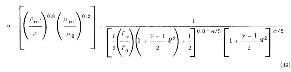
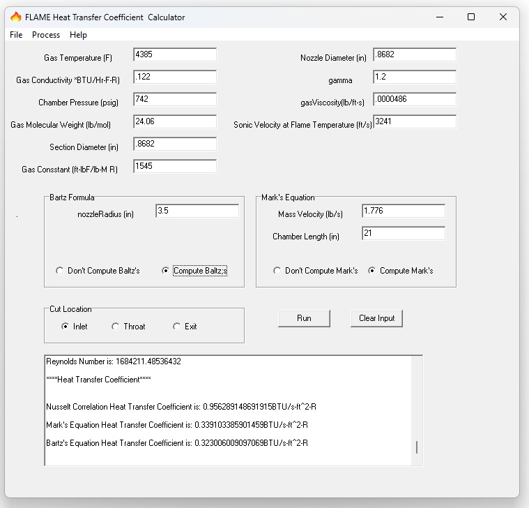
This equation can be solved using an Exel spreadsheet. I wrote a program called FLAME that solves it with less trouble. FLAME computes the heat transfer coefficient at the motor case, entry cone, nozzle throat and exit cone using the Bartz equation and two other methods, the Marks equations, and Wickman equations. Unfortunately, like the man with two watches who never knows what time it is, the HT analyzer with three coefficient methods never knows what the real heat coefficient is either, as the three rarely agree closely. Experience and forensic data from fired rocket motors is the only way to gain confidence in an estimation method.
However, this is only one of the problems confronting rocket motor heat transfer analysis. The second is that the requisite material properties (heat capacity, conductivity, decomposition temperature, heat of fusion, etc.) are only generally known for the materials used in rocket motor insulation. To make matters worse, the material properties change during the burn as the surface layer first chars, then flakes off during the burn. Modeling the material transformation with its associated change in material properties presents additional challenges.
The result is that insulation designs must either be destructively tested at subscale and full-scale motor firings to develop confidence, or else designed with a large safety factor. Heat transfer analysis can provide a starting point, and can also highlight suspected problem areas, but can only provide fairly accurate solutions when verified and calibrated against live fire forensic data.
Privacy Policy
Web site and all contents Copyright Explosives Consulting LLC. All rights reserved.


